|
NC30/NC35 Fuel Tap Vacuum Bypass
February 5, 2004
(click on image for a larger version)
A problem often found when racing an NC30 or NC35 is fuel starvation. This is a result of the vacuum valve of the fuel tap not allowing enough fuel to flow to the carburetors. The NC30 and NC35 HRC manuals recommend a change to the fuel tap that removes the vacuum valve to allow higher fuel flow. The procedure is very simple, but often hard to understand until someone shows you exactly how to do it. That’s the purpose of this web page.
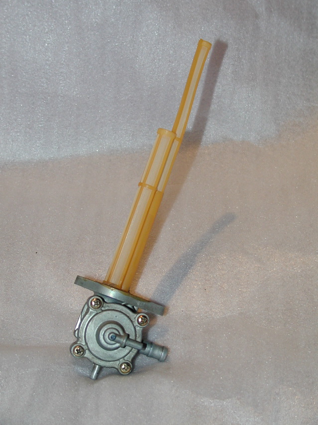
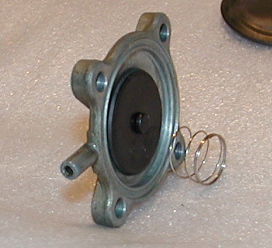
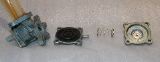
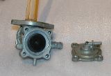
An NC30 fuel tap is shown to the right (removed from the fuel tank). The NC35 fuel tap is basically the same, and this procedure works for both types.
Three hose connections can be seen on the tap. The large connection to the right is the fuel output. The smaller connection on the center, pointing to the right, is the vacuum connection. This connects to the vacuum hose coming off the engine intake. The third connection, pointing down, is the bleeder hole. The bleeder hole may be shorter on some fuel taps.
As the engine turns, it creates a vacuum in the intake between the carburetor and the engine. A hose is run from the intake to the vacuum connection. Inside the fuel tap is a rubber diaphragm that is normally held closed by a spring, preventing fuel flow. When the engine is turning (by the starter motor, or because it is running on it's own), vacuum is generated that sucks the diaphragm out and allows fuel to flow. The problem is, the diaphragm does not allow enough fuel to flow during long term wide open operation, as is common for racing.
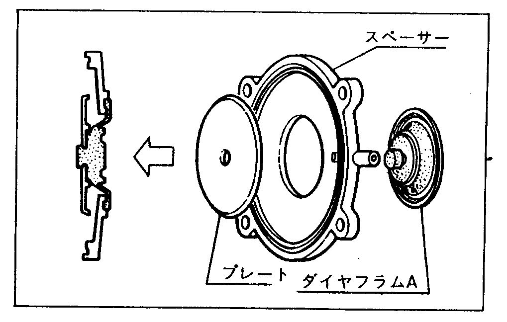 The Honda NC30 and NC35 HRC manuals show the diagram to the right to explain what must be done. Even if you can read Japanese, the text doesn't really explain it very well. The pictures and description here should help clarify things. The Honda NC30 and NC35 HRC manuals show the diagram to the right to explain what must be done. Even if you can read Japanese, the text doesn't really explain it very well. The pictures and description here should help clarify things.
The basic procedure is to disassemble the fuel tap, disconnect the small rubber diaphragm from the large rubber diaphragm and aluminum piece, disconnect the plastic piece from the large diaphragm, connect the plastic piece to the small diaphragm and re-assemble it, discarding the spring and large rubber diaphragm (including the little aluminum piece). The HRC diagram to the right shows the plastic piece and the small rubber diaphragm, but how you get to this arrangement is not so clear. Additionally, it is necessary to remove the vacuum hose from the intake and plug the intake hole with a screw.
Here is the procedure in detail. Text in blue represent the major steps.
 Remove the fuel tap from the fuel tank. Remove the fuel tap from the fuel tank.
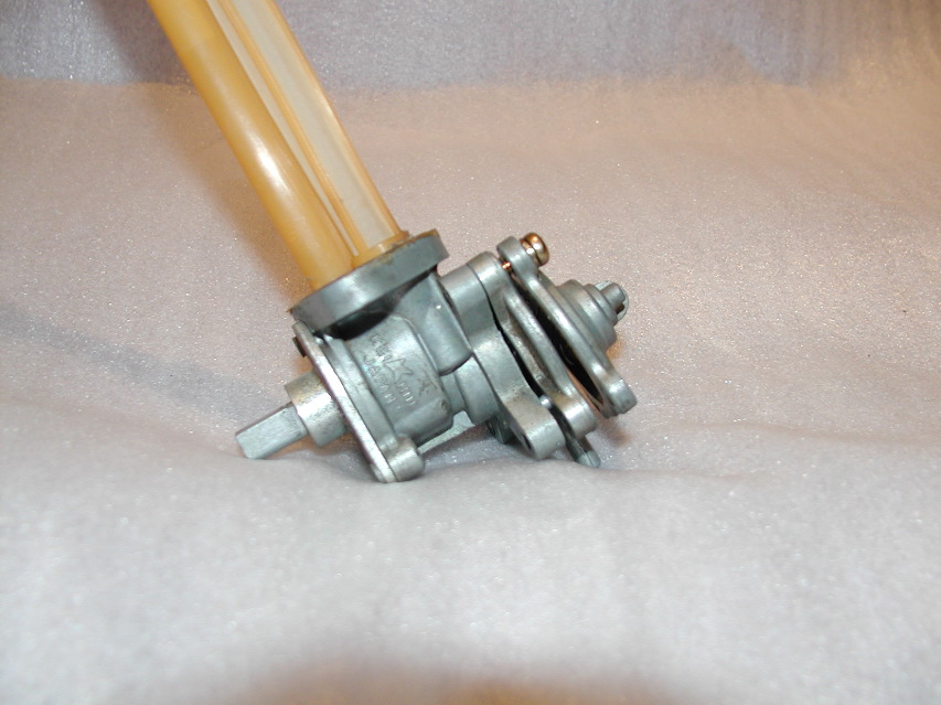
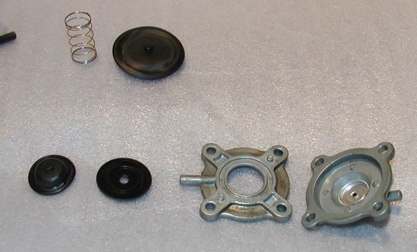
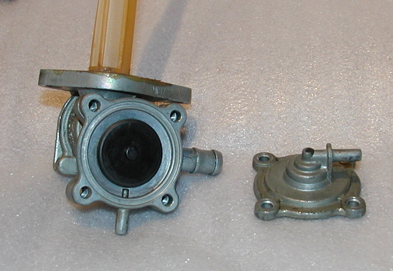
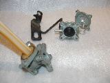
The fuel tap is made up of two plates (a middle plate, and an outer plate) and the actual tap or valve. The vacuum hose connects to the outer plate. Remove the four Phillips screws holding plates to the valve. The picture to the right shows the plates loosely held on by one screw. Once the last screw is removed, parts can fall out easily. Take it apart slowly so as to note how it goes together in case you have to reverse this procedure.
|
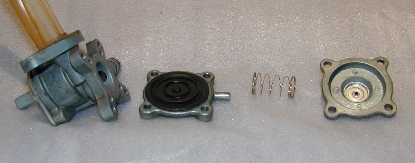
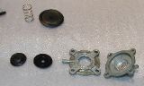
 Upon disassembly, you’ll have the parts shown here. There are two cavities, the vacuum cavity where the spring came from, and the fuel cavity on the other side of the middle plate. The spring normally presses on the plastic disc (shown), which presses the small rubber diaphragm (not shown) against the center hole of the fuel valve, preventing fuel from flowing to the outer ring of the valve and out the fuel output tube. The large rubber diaphragm (shown underneath the plastic disc) seals the vacuum cavity from the bleeder hole, which prevents vacuum from leaking to the outside air. Upon disassembly, you’ll have the parts shown here. There are two cavities, the vacuum cavity where the spring came from, and the fuel cavity on the other side of the middle plate. The spring normally presses on the plastic disc (shown), which presses the small rubber diaphragm (not shown) against the center hole of the fuel valve, preventing fuel from flowing to the outer ring of the valve and out the fuel output tube. The large rubber diaphragm (shown underneath the plastic disc) seals the vacuum cavity from the bleeder hole, which prevents vacuum from leaking to the outside air.
When the engine is turning, vacuum from the vacuum hose sucks the large rubber diaphragm away from the valve, which opens up the fuel flow.
|
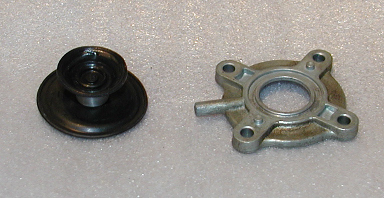
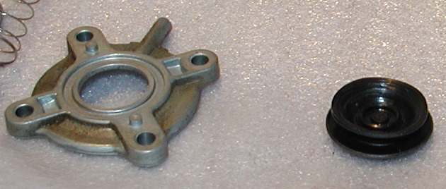
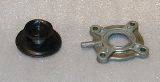
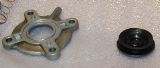
 This picture shows the smaller rubber diaphragm. This picture shows the smaller rubber diaphragm.
Bypassing the vacuum operation of the fuel tap requires removing the spring, modifying the rubber diaphragm and putting it back together such that it doesn't leak.
|
 Remove the rubber diaphragm assembly from the middle plate by pushing the smaller diaphragm through the center of the plate. Be careful not to damage the diaphragms. Remove the rubber diaphragm assembly from the middle plate by pushing the smaller diaphragm through the center of the plate. Be careful not to damage the diaphragms. |
 Remove the smaller rubber diaphragm from the rest of the assembly. It has a rubber foot inserted into the aluminum metal piece. Carefully pry it out of the metal piece. Remove the smaller rubber diaphragm from the rest of the assembly. It has a rubber foot inserted into the aluminum metal piece. Carefully pry it out of the metal piece. |
 Remove the plastic part that is attached to the large rubber diaphragm. Set the spring and large diaphragm (including the aluminum part connected to the large diaphragm) aside. They are no longer needed. Remove the plastic part that is attached to the large rubber diaphragm. Set the spring and large diaphragm (including the aluminum part connected to the large diaphragm) aside. They are no longer needed. |
 Push the small rubber diaphragm’s foot through the plastic piece's hole such that the flat side of the plastic piece faces away from the diaphragm. Refer to the HRC diagram above and the pictures for clarification. Note that the plastic piece is now facing the opposite direction compared to before with vacuum operation Push the small rubber diaphragm’s foot through the plastic piece's hole such that the flat side of the plastic piece faces away from the diaphragm. Refer to the HRC diagram above and the pictures for clarification. Note that the plastic piece is now facing the opposite direction compared to before with vacuum operation
|
| Push the small diaphragm back through the hole of the middle plate, like it was in the first place (diaphragm on the valve side, plastic piece on the vacuum side). Now, the plastic piece holds the small diaphragm in place instead of the aluminum piece and large diaphragm from before.
See the pictures below and duplicate what is shown.
It is possible to insert the foot of the diaphragm into the plastic piece through the metal plate in a single step. The pictures show it in two steps for clarity.
|
|
|
 Re-assemble the fuel tap, but without the spring, the large rubber diaphragm and aluminum metal piece connected to it. These pieces are no longer needed unless you want to convert back to a vacuum fuel tap. Re-assemble the fuel tap, but without the spring, the large rubber diaphragm and aluminum metal piece connected to it. These pieces are no longer needed unless you want to convert back to a vacuum fuel tap.
During re-assembly, make sure the small diaphragm outer edge seats into the groove of the middle plate. If the diaphragm is pinched in the wrong way, leaks will occur.
The small diaphragm side of the middle plate goes on the fuel tap side. The outside metal plate goes on the plastic piece side of the middle plate. Screw it all together, making sure not to pinch the rubber diaphragm in the wrong way.
|
|
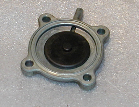
 Replace the fuel tap into the fuel tank, add fuel and check for leaks. Replace the fuel tap into the fuel tank, add fuel and check for leaks.
You no longer need a vacuum line from the engine to the fuel tap. You will need to remove the vacuum hose and plug the hole on the intake port. Follow the hose to the intake. Remove the hose. Remove the metal part the hose attaches to and plug the hole with an appropriate screw and washer (look at the other intakes for an example of the screw/washer). The vacuum hose cannot be attached to the fuel tap anymore. Since the large diaphragm was removed, attaching the vacuum hose to the fuel tap would allow open air to be sucked into the intake through the vacuum hose, adversely affecting the jetting for that cylinder.
After completing this procedure, the fuel tap should not leak, and if the carburetor floats and float needles are operating correctly, it should not overflow the carbuetors if left sitting for a while. Regardless, the fuel tap should not be left in the open position when the bike is not in use (close the valve at the end of a race day). Also, initially, monitor the fuel tap to make sure it doesn't develop a leak soon after making this change. Leaks may not appear until after riding for a while. Remember, you are disabling a safety feature. Act accordingly by being more cautious about how you use the fuel tap.
|
|
|