 |
||||||||
|
Mike's Honda VFR400/RVF400 Page
|
||||||||
|
||||||||
|
||||||||
|
Mike's Honda VFR400/RVF400 Page
|
||||||||
|
||||||||
Honda NC30 HRC Race Carburator SetupBelow are shown pictures of my race bike's HRC carburetor setup according to the NC30 HRC manual. The '92 NC30 HRC manual can be found here. Refer to the early part of the manual which explains these modifications. Unfortunately, the manual is in Japanese and I don't have a translation. For the NC30, the recommended configuration for racing was to remove the airbox and modify the carburetor bracket as shown below (drill the side holes and cut out the bracing between the carburetor pairs - see the pictures to understand better). Additionally, Honda provided a fiberglass tray (air scoop) that goes underneath the carburetors and extends through the opening between the top of the upper radiator and the bottom of the triple clamps. This air scoop brings fresh air into the cavity created by the air scoop and the underside of the fuel tank. The insulation on the underside of the fuel tank is removed so that it doesn't break up and get sucked into the carburetors. The underside of the HRC air scoop is covered with silver foil to reflect heat away from the carburetors, fuel tank and air cavity (UPDATE: This foil was added by a previous owner of the bike - the HRC air scoop does not have heat shielding foil). The stock NC30 also has an air scoop, but that scoop directs cool air over the top of the engine and the carburetors to keep them cool, rather than directing fresh air into the stock airbox. The fuel tank on a stock NC30 is kept cool by the insulation material attached to the underside of the tank. For comparison, pictures are shown of the NC30 stock and HRC carburetor setup as well as a stock NC35 carburetor (all shown without an airbox). A big change with the NC35 is the use of metal intake velocity stacks that point at an angle. This angle matches the intake angle of the carburetor, creating a more straight path for the air flow into the carburetor. The NC30 and NC35 airboxes are essentially the same. But, the NC30 and NC35 HRC carburetor setup is very different. For the NC30, the manual recommends removing the airbox, replacing the velocity stacks with the short rubber HRC boots shown below and running with no filter. For the NC35, however, Honda designed an HRC airbox/filter to replace the stock airbox. Unfortunately, I don't have pictures of the NC35 HRC setup. None of these setups are real ram air systems. All the scoops do is provide fresh cool air. Also shown are pictures of the two types of carburetors slides I have. The stock NC30 slide has a flat bottom, but the alternate part I have on my race bike (which I believe is an HRC part) has a rounded bottom. Hopefully the pictures and captions are self explanatory regarding the benefits of the HRC part. Interestingly, the stock NC35 carburetor slide is rounded, just like the NC30 HRC slide. (UPDATE: I have since been told that the NC30 slides with the rounded bottoms are in fact HRC parts). Note the two little holes on the bottom of the HRC slide (just in front of the jet needle) vs. the single hole on the stock slide. These holes control the rate at which the slide will react to pressure changes in the carburetor body, such that the slide does not fully open until the engine's RPM requires it. This prevents bogging. When you twist the throttle, a butterfly valve opens, but this doesn't actually open up the carburetor because the NC30 uses CV (constant velocity) carburetors. In a CV carb, as the engine speeds up, it increases the vacuum through the carbs. This pressure change propagates to the upper side of the slide (which is a sealed cavity) through the little holes . The vacuum causes the slide to be sucked upward, which opens up the carburetor throat and allows more fuel/air mixture through. For race purposes, larger (or more) holes are needed to increase the responsiveness of the slide. Hence, the HRC part has two little holes. A similar affect can be obtained with a stock slide by drilling out the hole (which is 2mm normally) to 2.5 mm. The last picture shows the NC30 jet needles, a stock needle, an needle of unknown origin, and an HRC needle. The Honda needles use shim washers to set the height whereas the unknown needle uses a clip. The needles in the picture are placed in order to show their relative height as if they were installed in the carb slide. Notice the HRC and unknown needle are shorter, causing a more rich mixture than compared to the longer stock needle. In summary, the NC30 HRC carburetor setup involves these changes:
I believe that is it. The NC35 HRC setup is basically the same, except you don't modify the carb. bracket or replace the velocity stacks. Instead, you use the HRC airbox, which includes a filter. I am currently running the HRC setup on my race bike, but I plan to move to an NC35 like setup as I would prefer to run a filter. (click on image for a larger version) |
||
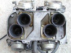 Stock NC30 Carburators looking down from top with the air box removed. Note the rubber intakes point straight up, causing a bend in the intake path. |
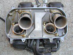 Stock NC35 carburetors with airbox removed. The NC35 intakes are metal, and they point straight out of the carb throttle body (no bend). (top of picture is front of bike) |
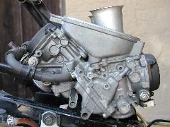
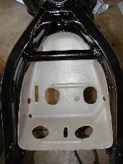
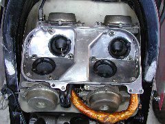 NC30 HRC carburetor setup. The velocity stacks are replaced with HRC short rubber boots. The airbox is discarded for this configuration (no air filter either). Instead, the white HRC tray is placed beneath the carbs. The "airbox" is made up of the cavity between this tray and the underside of the fuel tank. Note the holes drilled on the side of the metal bracket, and the ribbing is removed between the intake pairs. |
 NC30 stock carbs with airbox removed (right side), showing side view of carb bracket and velocity stacks. |
 NC35 stock carbs with airbox removed (right side), showing side view of carb bracket and velocity stacks. |
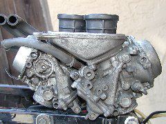
 NC30 HRC carb setup side view (right side). Note the silver underside of the air scoop/tray. This is heat shielding to keep the carburetors and fuel tank cool. The scoop does not come with this foil. It was added later. |
 NC30 HRC carb setup side view (left side). |
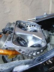
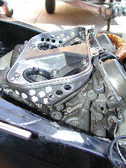
 Closeup of the hole pattern for the HRC modified carburetor bracket (right side). The left and right sides are drilled the same way. |
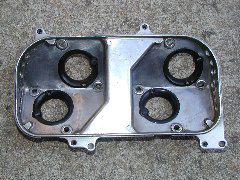 Another view of the HRC modified bracket. |
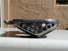
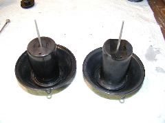
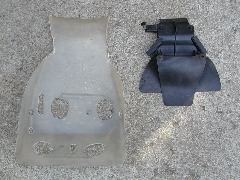 HRC fiberglass air scoop (left) and stock NC30 scoop (right). The top of the picture is the front of the bike. This HRC scoop is a copy of a real HRC scoop. |
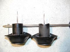
 Air scoops looking at them from the front view. |
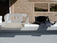
 Stock NC30 air scoop mounted in a frame (no engine or carbs). Note the stock scoop directs air underneath the stock airbox (not shown) to cool the carbs, not into the airbox. |
 HRC air scoop shown in a frame with no engine or carbs. The HRC scoop brings fresh air to the carburetors and keeps the carbs cool. |
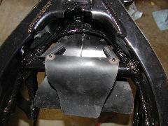
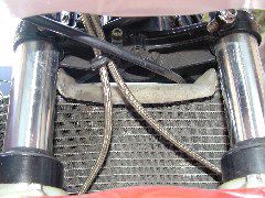 HRC air scoop shown looking between the forks. Both the HRC and the stock air scoops mount just over the top of the radiator, below the triple clamps. No picture of the stock air scoop is provided. |
 Two different NC30 carburetor slides (stock left vs. HRC slide right). Note the single hole vs. dual holes just in front of the needle. These holes affect the responsiveness of the slide (larger or more holes means a faster responding throttle). |
 Note also the right slide has a rounded cutout at the bottom of the slide (slides are shown upside down). |
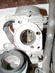
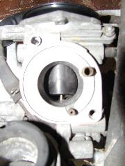 Stock NC30 slide shown looking through intake of carburetor. Throttle closed. |
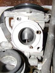 HRC slide shown looking through intake of carburetor. Throttle closed. |
 When fully opened, both slides move completely out of sight. Obviously, the HRC slide matches the roundness of the carburetor opening, providing smoother air flow compared to the flat bottomed stock slide. Note that the stock NC35 slide is rounded as well. |
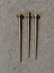 Three carburetor needles. Stock NC30 (left), HRC (right), and unknown (center). The needles are shown with the top spacers/clip matched as if they were in the slide. Note the HRC and unknown needles are shorter, allowing more fuel flow (more rich) at a given throttle opening. |
Posted 5/20/2003
Last Updated:
Email me at: mike@akhara.com